Configuration of Symbols
To create symbols it is necessary to select a single connection in the filter bar. In the example it is the NB200 UA Demo connection which is a OPC UA connection on the CollectorPowerbox Data Collector.
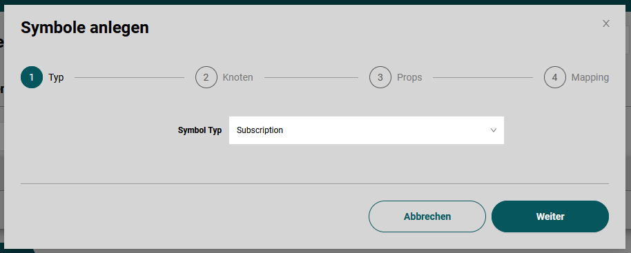
Pressing the "Create Symbol" opens the (connection specific) wizard.
Create OPC UA Subscription Symbols
A OPC UA Subscriptions samples a single OPC UA nodes and collects the data. The data can then be written by an output symbol, e.g. an Influx measurement.
Select the symbol type Subscription.
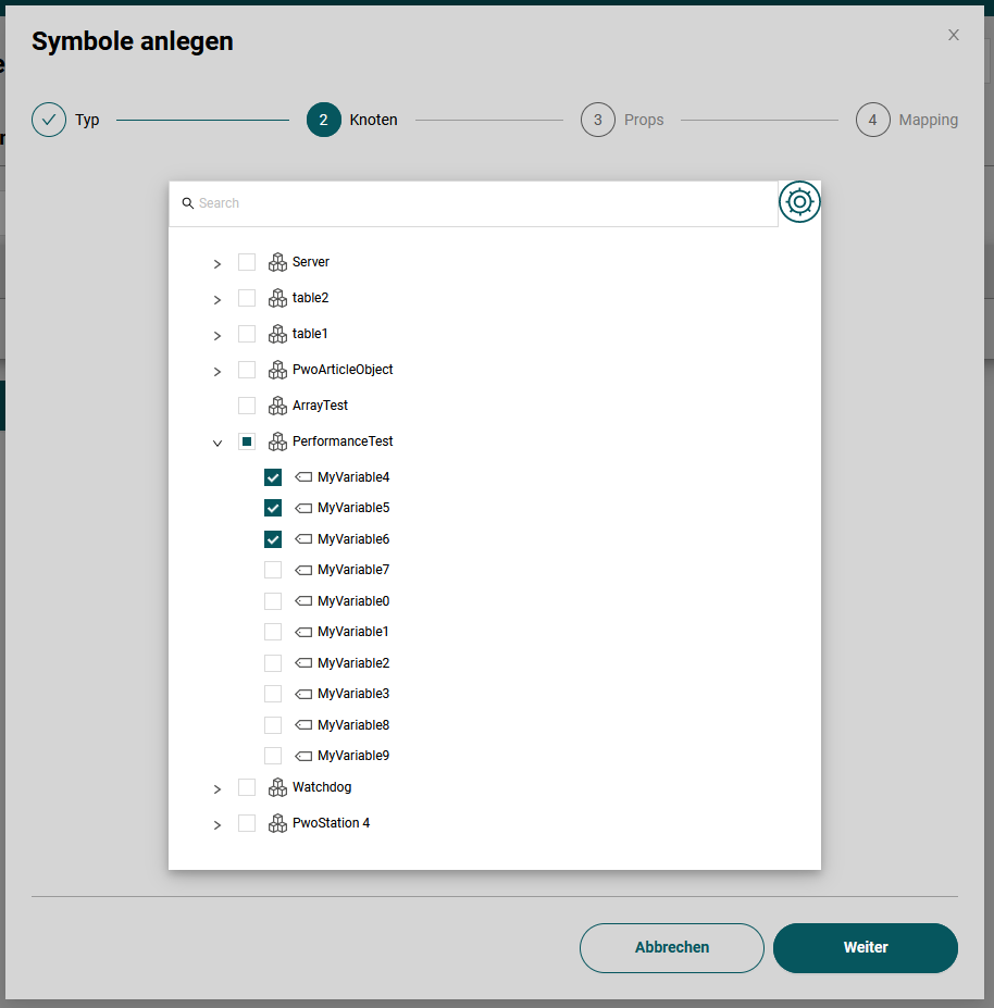
The OPC UA address space will be browsed and displayed. Select the nodes you like to sample.
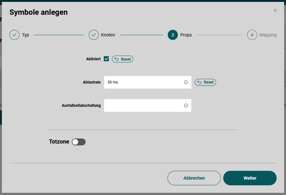
Set additional properties such as sampling interval.
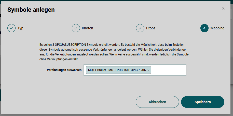
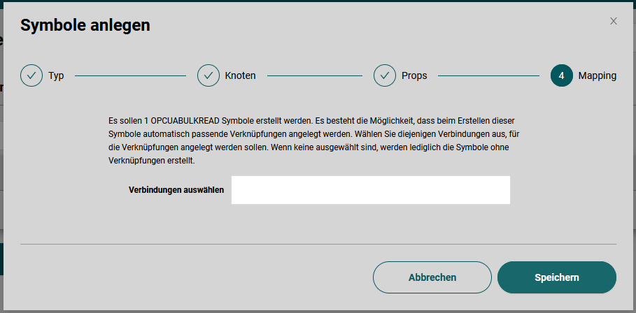
Configure auto mapping from the created input symbols to one or more output symbol of a specific type. In the example, the collector creates a MQTTPublishTopicObject symbol on the connection 'MQTT Broker' and an Influx measurement on the connection 'Spectra Influx' for each selected node in the previous step.
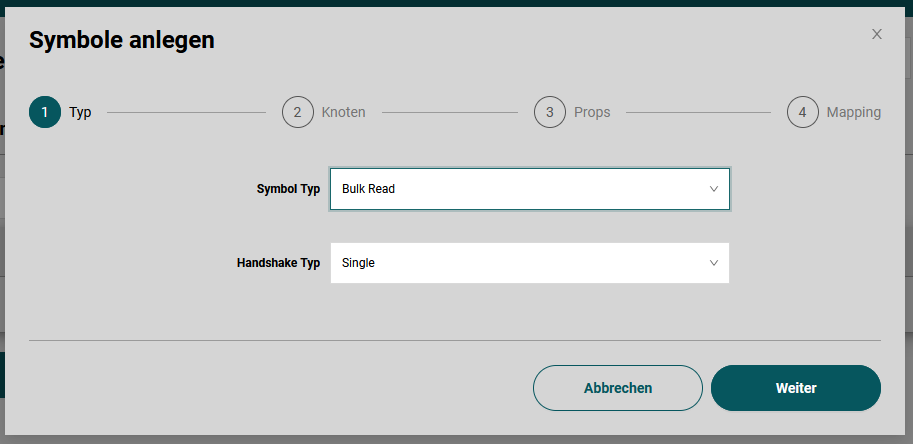
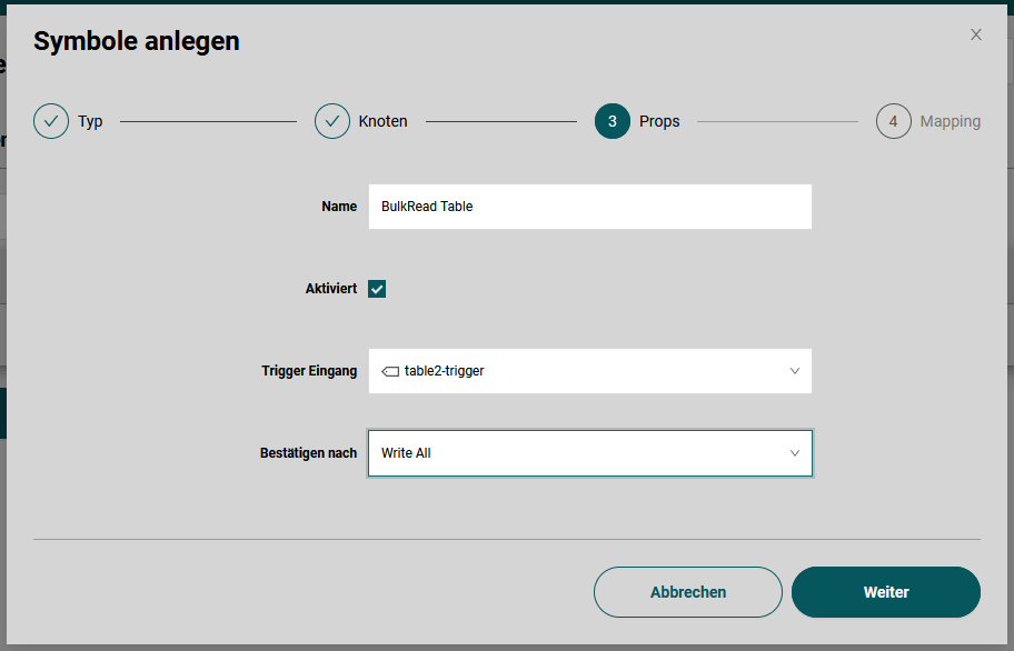
Create OPC UA BulkRead Symbols
The BulkRead symbol is used to read a set of OPC UA nodes as a single structure. The collector and the OPC UA server communicate a handshake to signal when data is ready to read and when the collector has processed the data point.
Select the symbol type BulkRead in the 'Create Symbol' wizard and select an appropriate handshake type.
The handshake type Single requires the server to have a writeable boolean OPC UA node that is set by the server to true when the values should be read. The collector reads the values and sets the handshake variable two false after the successful read or write.
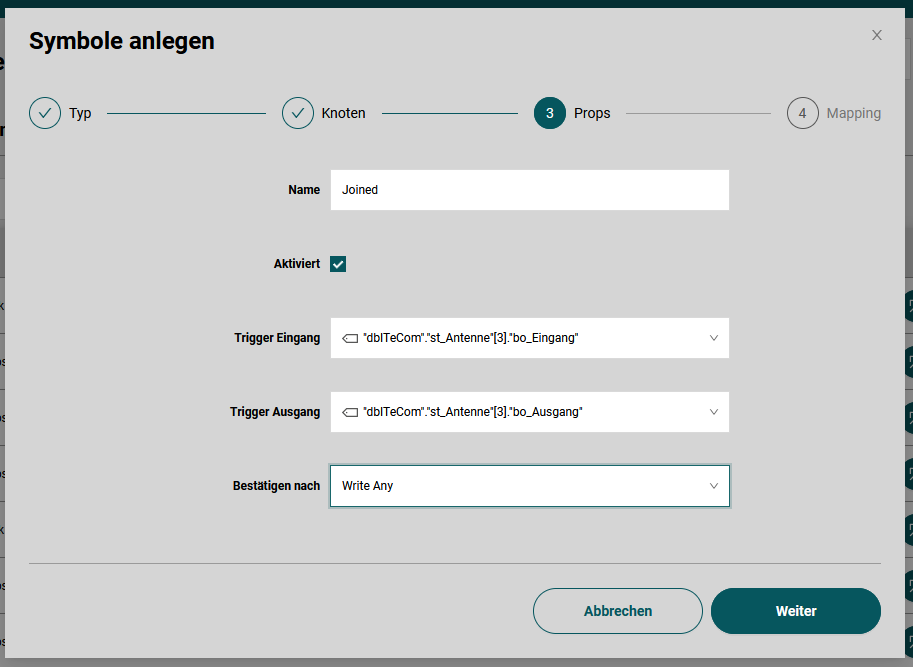
The handshake type Input/Output uses two boolean OPC UA nodes for the handshake. The OPC UA server sets the input OPC UA node to true when the collector should read the data nodes. The collector sets the output OPC UA node to true when the data points are successfully read or written. Then the OPC UA server must set the input node to false. Afterwards, the collector sets the output node to false, completing the handshake.
The handshake can be configured in both variants by specifying the 'Confirm After' type. With Read the collector confirms the handshake after successful read. The data point may not be written to an output symbol. With WriteAny, the collector confirms the handshake if at least one output symbol has written the data point successfully. With WriteAll the collector confirms the handshake if all output symbols have written the data point successfully.
Single Handshake Configuration
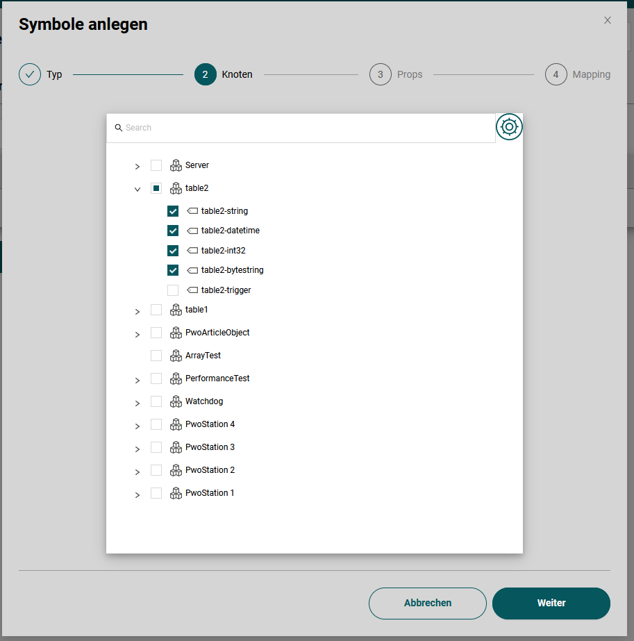
The OPC UA address space will be browsed and displayed. Select the nodes you like to sample. Do not select the trigger node but only the nodes that contain the data.
Select the trigger node.
Configure auto mapping from the created input symbols to one or more output symbol of a specific type. In the example, the collector creates a MQTTPublishTopicObject symbol on the connection 'MQTT Broker' and an Influx measurement on the connection 'Spectra Influx' for each selected node in the previous step.
Input/Output Handshake Configuration
The Input/Output handshake type is analogously configured as the single handshake type. The third page is different and allows to select the input and the output trigger nodes.
Note: Do not select the input and output trigger node on page two, otherwise you cannot select them on page three.
Influx1Measurement
Most of the time influx measurements will be created using the auto mapping features when creating one or more input symbols. However, often it is useful to create some measurements manually.
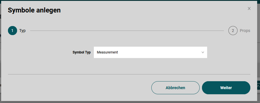
First select the influx connection that shall be used and create symbol. Select the symbol type Measurement.
In the wizard only the most basic settings must be filled.
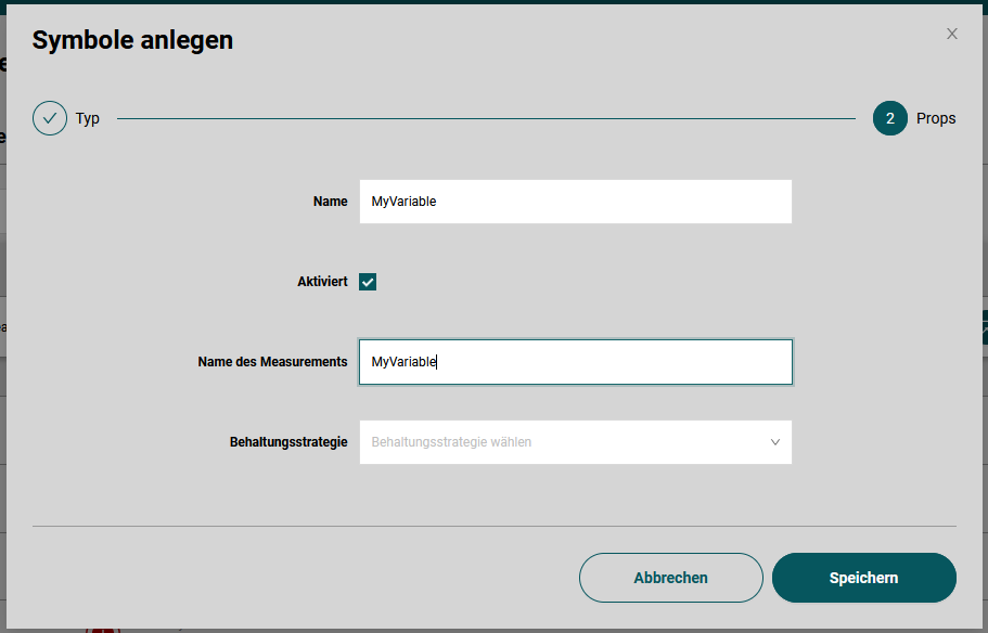
The Name will be displayed in the App. The Measurement name corresponds to the Influx measurement name. The retention policy can be left open and data points will be written in the default retention policy of the influx database.
Finally, the tags and fields can be configured in the created measurement. Click on the measurement to expand the tags and fields. New fields can be added using the last row.
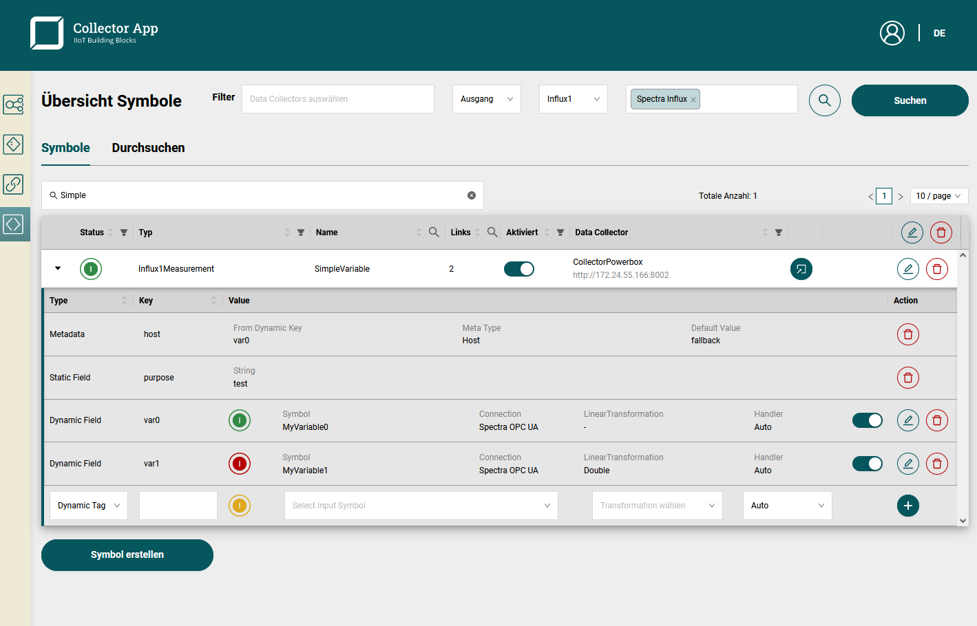
There are 5 types of configurable rows:
- Metadata: fills in metadata information from the selected input symbol. Provide a fallback value to prevent points to be discarded, when metadata is missing. An example for the metadata is the Host metadata which is used to tag the hostname of the connection of the input symbol. Only metadata of configured dynamic tags or fields can be used.
- Static field: A simple text that will be added as a field of the measurement. Note: currently only strings will be stored, even if the text corresponds to a number.
- Static tag: A simple text tag which will be added to the tag section of the measurement.
- Dynamic field: The data points of the configured input symbol will be inserted as the field with the configured key. It is possible to configure a linear transformation and restrict the type. In most cases it is useful to keep the auto type.
- Dynamic tag: The data points of the configured input symbol will be inserted as a tag with the configured key. The data type of the data points must be a number (integer, not a fractional), a boolean or a string. Other types are not supported as a tag. WARNING: Dynamic tags may reduce the performance of the influx database. For each unique tag value, a separate time series is used internally in the Influx database which restricts performance. However, the feature can be useful since Influx Queries can use WHERE queries on tags but not on fields.
Note that if multiple dynamic tags or fields are used, the restrictions of join functionality will apply.
Handling of Arrays in Influx Measurements
If a data point that should be written to a measurement field arrives, the collector creates multiple influx data points from the array. It uses the tag 'index' to identify the index of the single point in the array. If a static or dynamic tag is configured with the key 'index' it will be overwritten. Note that for each index a separate time series is created by the Influx database internally.
Handling of Structures in Influx Measurements
If a data point is a structure, e.g. through a OPC UA BulkRead or by the data type in a OPC UA Subscription, the structure can also be written in the influx database by flattening the structure. Only dynamic fields support structures; dynamic tags cannot be structures.
Take a look at the example structure (as json):
{
  "anInt": 3,
  "anBool": false,
  "nested": {
    "aString": "world",
  }
}
The corresponding line protocol for a dynamic field with key 'data' at timestamp 132909231230223 looks like:
name data_anBool=f,data_anInt=3,data_nested_aString="world" 132909231230223Note that arrays inside structures are not supported. However, an array of structures is supported.
Create MQTT Publish Topic Plain
Most of the time MQTT Publish Topic Plain will be created using the auto mapping features when creating one or more input symbols. However, often it is useful to create some symbols manually.
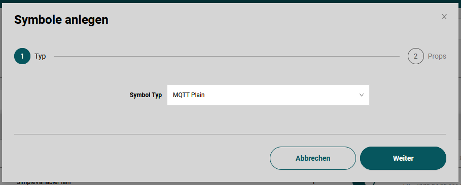
First select the MQTT connection that shall be used and create symbol. Select the symbol type MQTT Plain.
In the wizard only the most basic settings must be filled.
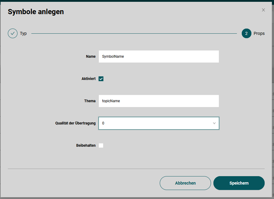
The Name will be displayed in the App. The Topic corresponds to the MQTT topic where the data points are published to. The quality of service can be configured. The retain flag can be configured as well.
Finally configure the input symbol in the expanded row in the symbols table.
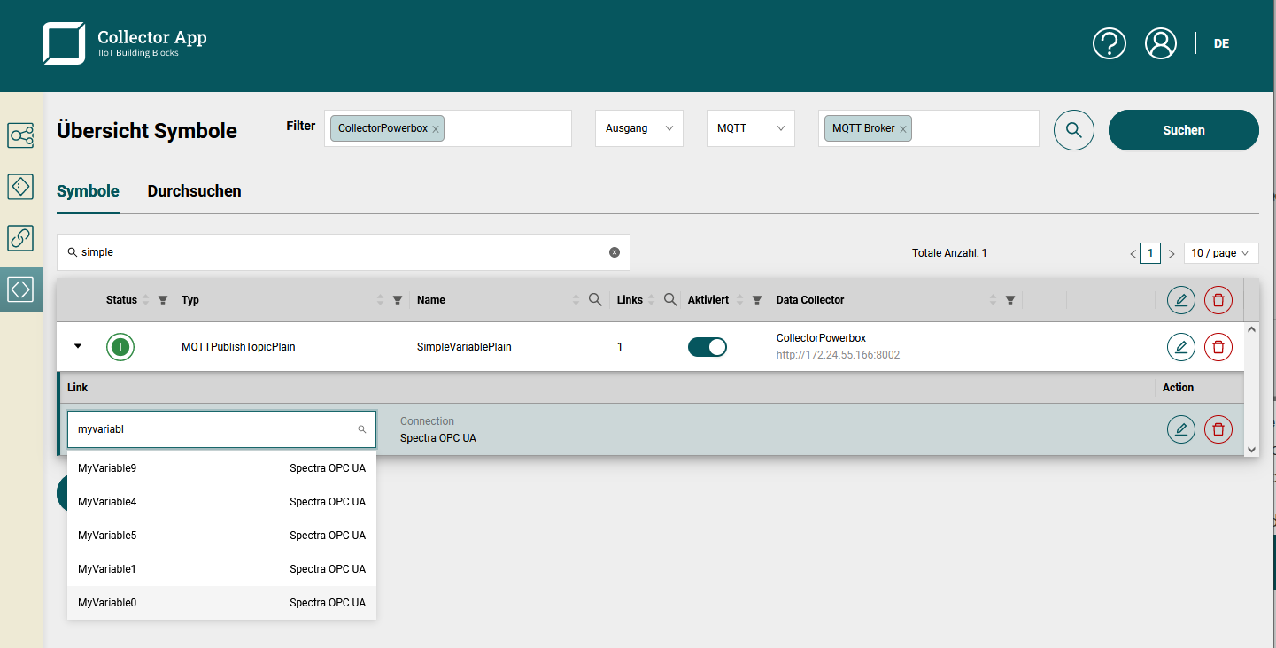
The data points will be written as json object. The keys of the json object can be configured. The result of a number data point will be the json
413658032"hello world"[1, 2, 3, 4, 5]{
"hello": "world",
"anotherKey": false,
"nested": {
"structures": 2,
"arePossible": -23.3
},
"anArray": [true, false, true, false]
}Create MQTT Publish Topic Object
Most of the time MQTT Publish Topic Objects will be created using the auto mapping features when creating one or more input symbols. However, often it is useful to create some symbols manually.
The data points are converted to json and the timestamp in (ISO8061) will be added to the object as well. An example of a converted data point is shown at the end of the section.
First select the MQTT connection that shall be used and create symbol. Select the symbol type MQTT Object.
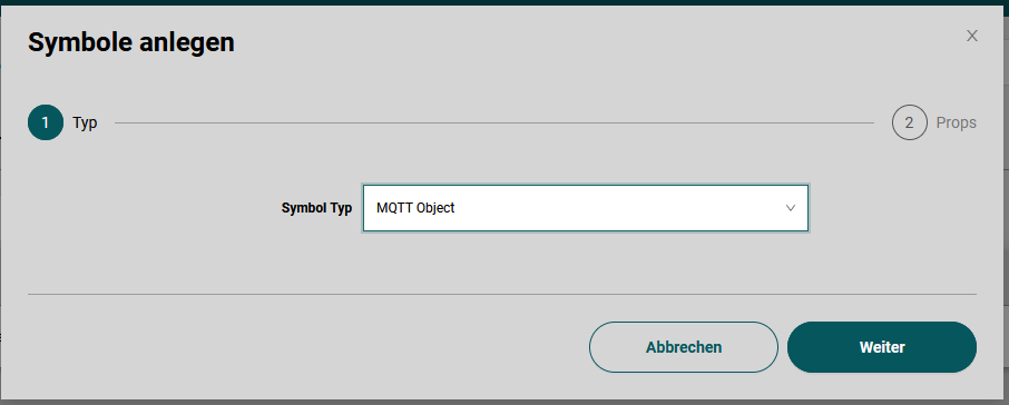
In the wizard only the most basic settings must be filled.
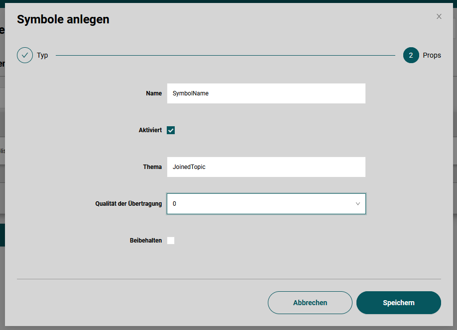
The Name will be displayed in the App. The Topic* corresponds to the MQTT topic where the data points are published to. The quality of service can be configured. The retain flag can be configured as well.
The data points will be written as json object. The keys of the json object can be configured.
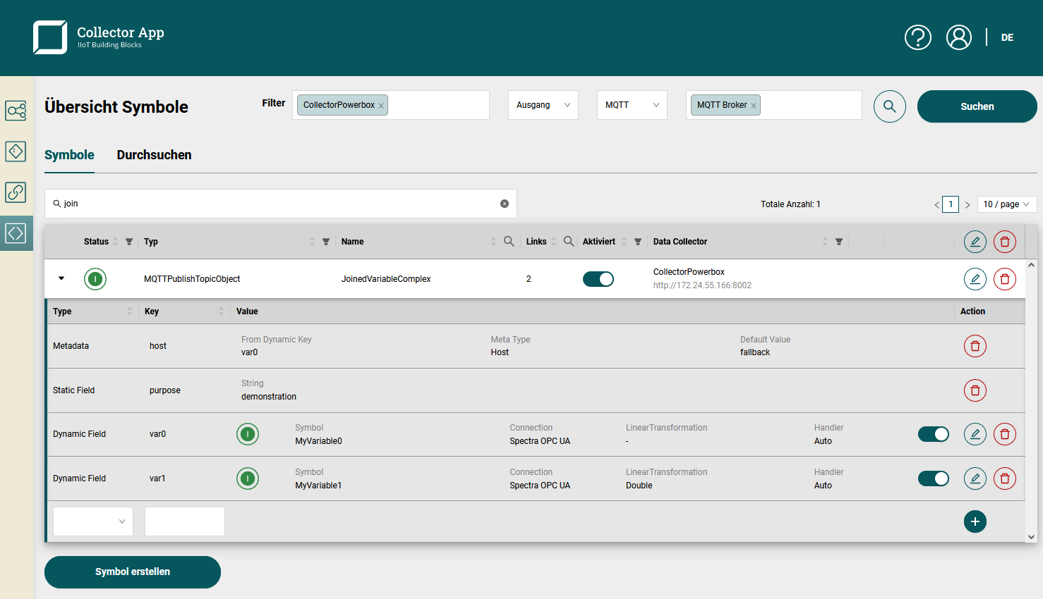
There are 3 types of configurable rows:
- Metadata: fills in metadata information from the selected input symbol. Provide a fallback value to prevent points to be discarded, when metadata is missing. An example for the metadata is the Host metadata which is used to tag the hostname of the connection of the input symbol. Only metadata of configured dynamic tags or fields can be used.
- Static field: A simple text that will be added as a field of the measurement. Note: currently only strings will be stored, even if the text corresponds to a number.
- Dynamic field: The data points of the configured input symbol will be inserted as the field with the configured key. It is possible to configure a linear transformation and restrict the type. In most cases it is useful to keep the auto type.
The result of the example configuration is:
{
  "host": "ite-si.de",
  "purpose": "demonstration",
  "timestamp": "2022-07-28T07:16:30.798761Z",
  "var0": 413658032,
  "var1": 827316064
}
Note that if multiple dynamic fields are used, the restrictions of join functionality will apply.
Restrictions of Join Functionality
The Data Collector allows to join data points from multiple input symbols on a best-effort principle. The join functionality can be used by specifying multiple input symbols in an output symbol. For an example see the configuration of an Influx1Measurement using multiple dynamic fields.
Best-effort principle means that the collector will join data points in the order that they are sent from the source to the data collector. This means that two data points are joined correctly if they have the same time stamp and arrive at the same time at the Data Collector. If two data points have the same time stamp but arrive with a jitter of 2 seconds, the joined data points will be incorrect until the second data point arrives. For most OPC UA servers, this is true for OPC UA MonitoredItems, which are used in the input symbol OPC UA Subscription.
If input symbols of different connections are used, joining will not be very accurate. The reason is that OPC UA transfers bulks of data points per OPC UA server. Most likely data points joined from multiple connection will very at least a few hundreds milliseconds, but may be inaccurate by multiple seconds. Moreover, connection losses on different OPC UA servers increase the inaccuracy even further.
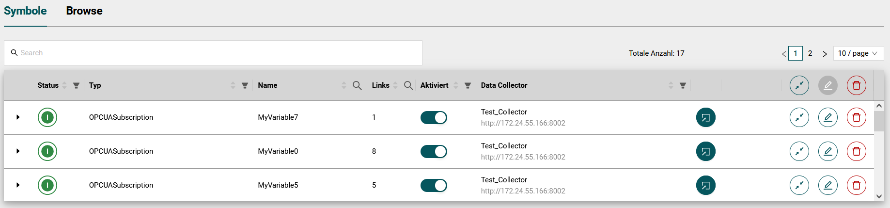
Set Mass Symbols
In the symbol table in the header there are buttons on the right, that can edit or delete all symbols in the table at the same time. These are called mass buttons.
A buttons that are located in a single row operates only on its symbol. A mass button operates on all symbols selected in the table. To operate only on a subset of the symbols, use the filter mechanisms of the search field and table header to select the symbols to modify. Note that all selected symbols are edited not only the visible page of the table. In the figure below, all symbols of table page 1 and 2 will be modified if the mass button is pressed.
Automapping Button
The automapping function allows you to quickly create for one or more input symbols one output symbol per output type. To do this, the connections of the output types must be selected.
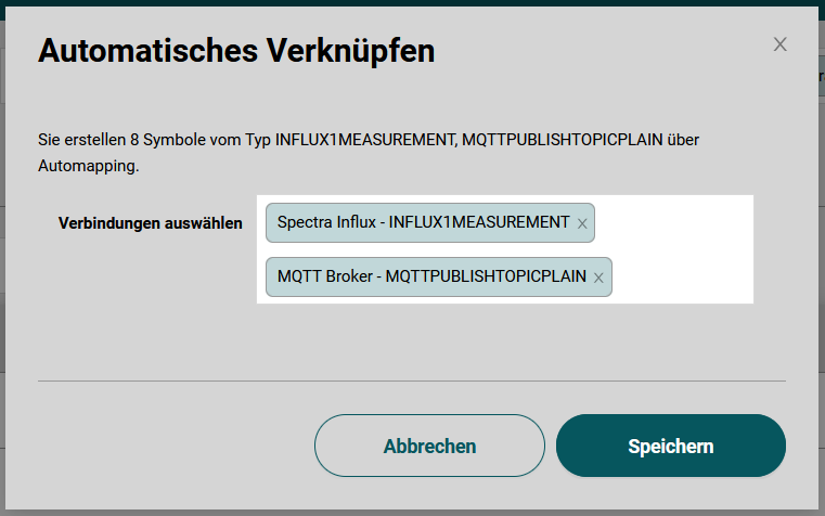
An automapping button in a symbol row will create an output symbol for each selected connection. Using the mass automapping button in the table header will create for each input symbol an output symbol for each selected connection.
Edit Button
The Edit button allows you to edit one or more symbols. For example an interval, a timeout and a deadband can be set for OPCUASubscription. In the normal editing function for single symbols, the deadband can be switched off by deactivating the switch and saving the modal.
Note that it is only possible to mass edit symbols of the same type. For example, if the table contains OPCUASubscription and OPCUABulkread symbols, the mass edit button will be disabled. Filter to a single type using the table header filter to enable the mass edit functionality in such a case.
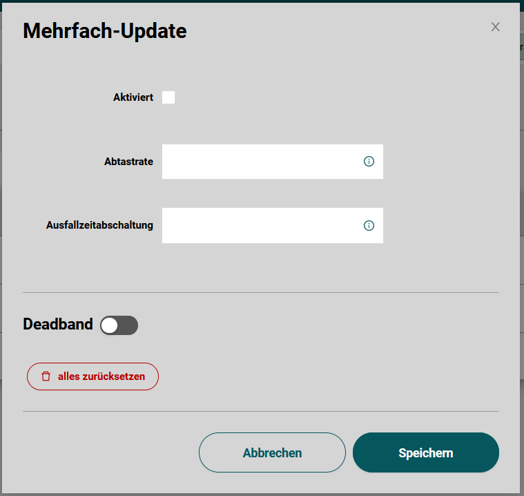
With the multiple edit function there is an additional button, with which the deadbands of all symbols can be reset at the same time. Here the modal must also be saved for the reset of the deadbands to be effective.
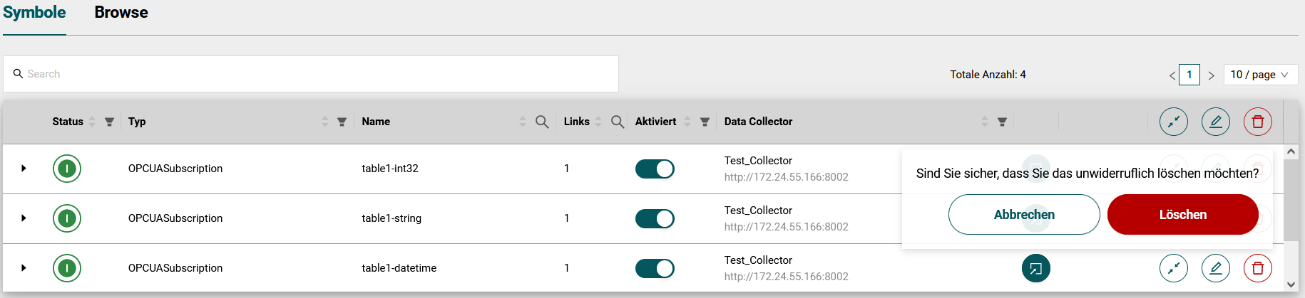
Delete button
The Delete button allows you to delete one or more symbols. Individual symbols are deleted by the delete button in the respective symbol line. If the multiple delete button is pressed in the header then all symbols listed in the table will be deleted at the same time.
In order to avoid deleting something by mistake, the user must confirm the delete action in the popup dialog before the symbols will be deleted.